Official PN26 Electronic Badge
I always enjoy bringing fun hardware projects to cons like PhreakNIC (or our not-a-con "Barely-a-Con"), and have done some level of that for the past few years. Fancy electronic badges like my Magic 8-Badge are fun, but increasingly expensive due to higher tariffs and overseas shipping costs from my go-to PCB fabricators. Even a couple of bucks each adds up for a small con with ~200 people, so we were looking to figure out if it was possible to build something super cheap but still fun.
We were able to build 200 3D-printed pager-styled, battery-less, programmable badges where attendees could choose a custom image background and name to display on the screen.

One Tuesday night, we were chatting about power budgets vs money budgets for various displays. While e-paper displays are awesome for low power devices, they're not particularly cheap, even as prices continue to drop. I was looking into working out a quick parts list for a badge using a small LCD screen, when I remembered some fantastic work done by atc1441 on repurposing old electronic shelf labels (ESLs) like you'd find at a grocery store or Best Buy. I hopped on eBay and one particular listing caught my eye:

100 ZBD 55c-RB shelf labels with dead batteries for less than $70 shipped? Pretty darn good deal, and giving a second life to what would otherwise become e-waste is a wonderful bonus! I looked around for the model number on the Internet a bit and didn't find a ton of information, but luckily I ran across this awesome work by Dmitry Grinburg on hacking all sorts of ESLs. That page listed a really thorough investigation and source code for the ZBD EPOP50, which appears very similar to the EPOP55s on eBay.
After reading through the technical details and taking a quick look through Dmitry's source, I decided to go ahead and buy 100 of those EPOP55s.
The Teardown
I was hoping that these tags would have replaceable batteries, which could also give us easy access to the programming pins, but no such luck here. In fact, these were completely glued or sonic-welded shut and were kind of a pain to get into.
The best way I found to open it up was to snip the plastic bezel with some flush cutters, and pry off the front plate.
Once you get into the casing, there honestly isn't a ton in there. You've got a TI CC1110 microcontroller running everything and providing the subGHz radio communication, and two coin cell batteries to power it. According to the ZBD sales sheet, they should keep these tags alive for around 10 years, which explains why they'd be put up on eBay ~10 years later.
The exciting part though, to me at least, is the screen! ZBD developed a bistable LCD which isn't the same as e-paper, but has a bunch of similar characteristics.
They hold whatever image you display on them, even after you remove power, which helps with getting that 10 year battery life.
They don't have the contrast or readability of e-paper and don't support greyscale, but they're fast to update, especially as far as 15-year-old display technology goes.
Pinout
On the PCB, there are a few exposed pads that would presumably allow us to flash our own programs and hopefully give access to a serial port and a couple of GPIO pins. After manually tracing these pads out to pins on the CC1110, I was able to verify that we had the debugger/flasher pins, a UART TX/RX pair, and a couple of spare GPIO pins.

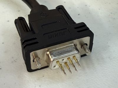
These pads are pretty close together, but thankfully every other pad was duplicated a small distance away. That layout was a little strange, but my friend Mog noticed that the spacing happened to line up with the pins in a DB9 connector (or "DE9" if you wanna get pedantic about it). That made it easy to shove some 1 mm pogo pins into the end of a DB9 cable for programming.
Flashing with a CC Debugger
I started out using a TI CC Debugger I got off of Amazon for about $15 since it seemed like it would be the most likely option to be successful and was referenced on Dmitry's page. Just like the other ZBD EPOP tags that Dmitry investigated, the flash space was not locked, so I was able to extract the stock firmware in case it might come in handy later.
I made some minor tweaks to Dmitry's firmware to handle the different screen resolution, built the binary, and flashed it using cc-tool. Success! I played around with drawing text and images onto the screen, and then went and bought a few hundred more tags.

Flashing with ESP32-S2
We eventually wanted to be able to do more than the CC Debugger would allow, though.
We wanted to build little programming stations that could pull images from the Internet and send them to the tag, as well as serial debugging and communication. I didn't want to have to dedicate an entire Raspberry Pi or other SBC just to handle USB communication, either.
Luckily, again, atc1441 has already helped us here! atc1441's ESP CC Flasher is an Arduino program that lets you flash a CC1110 using an ESP32 WiFi microcontroller. Once Mog proved it worked, I put aside the CC Debugger and used this almost exclusively from then on, even though it was a little slower to flash.
We made some changes to remove some of the lower-level debug functionality and added some extra serial handling from the tag.
The Firmware
The idea for the PhreakNIC badge was to allow an attendee to scan a QR code on the back of their badge, which would take you to a website that would allow you to select a "frame" (background image) and configure your name and its size and positioning.
Special shoutout to Nathan for building out that site! And for dealing with all of our last-second requests for changes and additions...
The firmware we built ended up being a little simpler than expected, but still worked well enough to give attendees a fun, customizable experience!
When you place the badge on one of the programmer stations, it boots up and displays a hardcoded image on the screen. Then it starts sending out its MAC address and a hash of the image via the UART serial port at 9600 baud. The original plan was to have an ESP32 in the station listening for those MAC and hash messages, and query our backend API for a new firmware file. If the downloaded firmware had a different image hash than what was on the badge, the ESP would start flashing the new firmware file to the badge.
We had that working pretty well, but we weren't able to build a programming station that was reliable enough to line up the tiny pogo pins with the tiny pads reliably, given the tolerances of FDM-printed cases, in time for the conference.
Instead, we used a bluetooth barcode scanner and a simple script that pulls down the appropriate firmware for the scanned badge and uses cc-tool with a CC Debugger to flash the badge.
Either way it required a mechanism for building custom firmware files!
Building Custom Per-attendee Firmware Files
As mentioned earlier, the base firmware was designed to display a single static image right at boot. In order to update the image, we would take the base firmware, patch in a binary replacement of the 1-bit image data, and flash the new patched firmware to the badge. A pair of magic strings would be prepended and appended to the image data so that a script would have no trouble finding where the replacement should happen.
We also did the same with a hash of the image data; wrapped it in some magic strings so that we could inject that into the firmware and then the badge would print that hash out of its serial port. This let the ESP32 in the originally-planned programming station know what image was currently loaded on the badge and prevent it from re-flashing the firmware with an image that is already loaded.
This setup made it really easy to write a quick little Python script that would take in a 240x96 image and a base firmware, convert the image to 1-bit binary data, and return a patched firmware. This script could be run locally or in the backend of the web application. For the web application we'd save the Base64-encoded firmware data whenever the user updated their badge design.
A fun benefit to this was that we could make changes to the base firmware and push those updates out to badges through the normal patch-and-flash process. On the flip side, flashing a new firmware every badge update took a bit longer than doing something like updating an image in the EEPROM, and it made it possible to leave a badge in a broken state if the flash process was interrupted.
Shoutouts and Thanks
I also want to shout out to all of the wonderful people who directly or indirectly helped make this possible!
- Nathan - for building the whole web application for configuring the badge images, and staying up late-late the night before the con helping debug ESP32s.
- Mog and Heather - for designing and 3D printing hundreds of badge cases, shucking ESL enclosures, and assembling all of the physical parts.
- atc1441 - for the initial inspiration to look into ESLs, and the ESP CC Flasher tool that we will definitely be using more of!
- Dmitry - for all of the amazing reverse-engineering work that made this all possible. I don't know if I would have even attempted this if it weren't for the excellent source code and documentation to build off of.
What's Next?
Ultimately, we got around 200 finished badges to PhreakNIC with a bunch of different colors of 3D printed cases (with unique 3D printed QR codes on the back!). I set up at one of the tables with my barcode scanner, programming jig, and flashing script, and people would bring their badge to get updated. It gave me lots of opportunities to chat with people who were excited about how it all worked, so it ended up being even more fun than having a self-service station available.
It was such a hit that we've already started planning for next year's version! People appreciate being able to reuse something otherwise destined for the trash bin, and the conference organizers appreciated that we could put together something cool for PhreakNIC without spending a ton of money.
I may have already bought out the rest of the tags from that eBay listing... 😅
Things we definitely want to try to get working for next year:
- EEPROM storage of images instead of the firmware patching hack we used. There is a good bit of space available for data, and Dmitry's code examples already take advantage of this.
- UART/wireless communication, which would be needed for more dynamic interactions, like the update stations we were hoping to have this year.
- Self-service update stations so attendees can update their badges without having to wait on me to be available to change the frame or text on their badge. Looking to utilize wireless for this so the station only needs to apply power to the two giant power pads on the back of the board.
- Specialty stations that can be integrated with other hardware, puzzles, or games. A cool example is a "photo booth station" that lets you take your photo for an ID-card-style frame.
Stay tuned, and hopefully I'll be bringing an even cooler MK.II to everyone next year at PhreakNIC 27, which is currently scheduled for Nov 6-7, 2026! Keep an eye on the PhreakNIC website for more details as they are made available.
♥ tyler crumpton